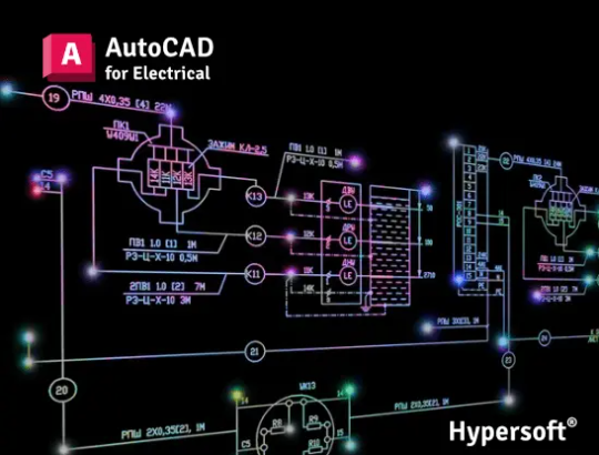
Auto Cad Electrical Course in Visakhapatnam | An AutoCAD Electrical course teaches engineers and designers how to create and manage electrical control systems and schematics using specialized software. Programs are available online and offline from various training centers and educational platforms.
Key Course Content :
A comprehensive AutoCAD Electrical course typically covers the following topics:
- Introduction to the interface: Auto Cad Electrical Course in Visakhapatnam | An overview of the AutoCAD Electrical user interface, including how it differs from standard AutoCAD.
- Project management: Setting up and managing electrical projects and drawings.
- Schematic design: Inserting components, working with wire and ladder diagrams, and creating and modifying circuits.
- Symbol libraries: Using and creating custom electrical symbols.
- PLC modules: Generating, inserting, and editing PLC (Programmable Logic Controller) layout modules and managing PLC database files.
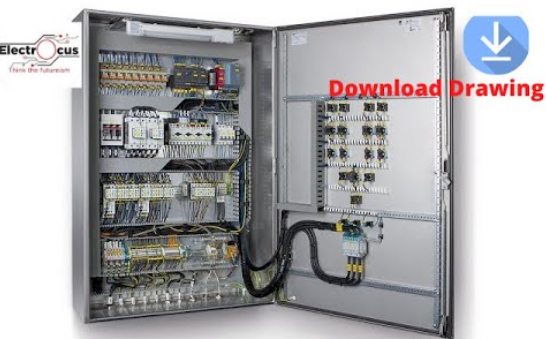
- Panel layouts: Creating and modifying control panel layouts, including inserting footprints, DIN rails, and wire annotations.
- Reporting and documentation: Generating reports, such as Bill of Materials (BOM), from the design files.
- Cross-referencing and tagging: Auto Cad Electrical Course in Visakhapatnam | Automatically assigning wire numbers and component tags and creating cross-references.
- Auditing drawings: Learning how to check for errors and missing catalog data.
- Best practices: Implementing industry standards and automated tasks for enhanced productivity.
Who should take this course?
This course is ideal for a range of professionals and students:
- Electrical and Electronics Engineers
- Designers and Draftsmen
- Undergraduate and diploma students in related fields
- Technicians looking to upgrade their skills
- Anyone involved in designing and drafting electrical control systems
Auto Cad Electrical Course in Visakhapatnam | Of course. Here is a comprehensive and structured outline for an AutoCAD Electrical Course, designed to take a student from foundational concepts to proficient use in creating and managing electrical control system designs.
Course Title: AutoCAD Electrical: Automated Control System Design & Documentation
Target Audience: Auto Cad Electrical Course in Visakhapatnam | Electrical engineers, electrical designers, control panel builders, automation technicians, instrumentation engineers, and drafters in the manufacturing, industrial automation, and power systems fields.
Prerequisites:
- Basic computer literacy (Windows OS).
- A fundamental understanding of electrical engineering principles, especially electrical controls (ladder logic, relays, sensors, PLCs).
- Familiarity with basic AutoCAD is helpful but not mandatory.
Course Goal: Auto Cad Electrical Course in Visakhapatnam | To equip students with the skills to efficiently create, modify, annotate, and manage intelligent, standards-compliant electrical control drawings, generate reports automatically, and drastically reduce errors and drafting time.
Detailed Course Modules
Module 1: Introduction to AutoCAD Electrical & The Interface
- 1.1 What is AutoCAD Electrical (ACE)? Understanding how it differs from vanilla AutoCAD. Overview of its intelligent, database-driven functionality for electrical design.
- 1.2 The ACE User Interface: Auto Cad Electrical Course in Visakhapatnam | Navigating the specialized ACE ribbon tabs (Schematic, Panel, Reports), the Project Manager, and the Tool Palette.
- 1.3 The Project Manager: The core of ACE. Understanding the project (*.wdp) file structure, which manages all drawings, components, and reports.
- 1.4 AutoCAD Electrical Projects vs. AutoCAD Drawings: The critical difference between a set of DWG files and an ACE project.
Module 2: Project & File Management
- 2.1 Creating a New Project: Setting up a new project, defining its properties, and assigning a description.
- 2.2 Project-Wide Settings: Configuring default paths, drawing templates, and title blocks.
- 2.3 The Drawing List: Managing the sequence of drawings within a project.
- 2.4 WDF Project File: Understanding how the project file links all drawings and components.
Module 3: Schematic Wiring Diagrams (Ladder Logic)
- 3.1 Inserting Wires: Using the intelligent wire tool. Understanding wire types and layer conventions.
- 3.2 Inserting Components: Using the Icon Menu to insert intelligent schematic symbols (contacts, coils, relays, sensors, PLC I/O) from manufacturer-specific libraries (JIC, IEC, NFPA).
- 3.3 Component Intelligence: How symbols carry metadata (catalog number, manufacturer, description, ratings).
- 3.4 Wire Numbering: Using automatic wire numbering. Setting up wire number formats and layers. Understanding phase and wire type.
- 3.5 Ladder Tools: Using the “Insert Ladder” tool to quickly create and modify rungs. Setting rung spacing and numbering.
Module 4: Component Editing & Management

- 4.1 Editing Components: Using the “Edit Component” tool to modify attributes like catalog data, ratings, and descriptions.
- 4.2 Cross-Referencing: The power of ACE. Automatically generating and updating cross-references for contacts and coils (e.g., showing where a relay coil CR5 is and where all its NO and NC contacts are used).
- 4.3 Parent/Child Relationships: How ACE maintains the intelligent link between a component (e.g., a relay coil) and its related components (its contacts).
- 4.4 Retagging (Renaming) Components: Using project-wide retagging tools to automatically rename components and update all references.
Module 5: Panel Layouts (Enclosure Drawings)
- 5.1 The Panel Layout Environment: Switching to the Panel tab. Inserting footprints from the icon menu.
- 5.2 Schematic-to-Panel Link: How ACE links schematic components to their physical footprint in the panel layout.
- 5.3 Inserting Footprints: Placing DIN rail, terminal blocks, pushbuttons, and other components. The importance of the “Scale” factor.
- 5.4 Ballooning: Automatically generating balloons with component tags for the panel layout.
- 5.5 Back-Annotation: Ensuring changes in the panel layout are reflected in the schematic.
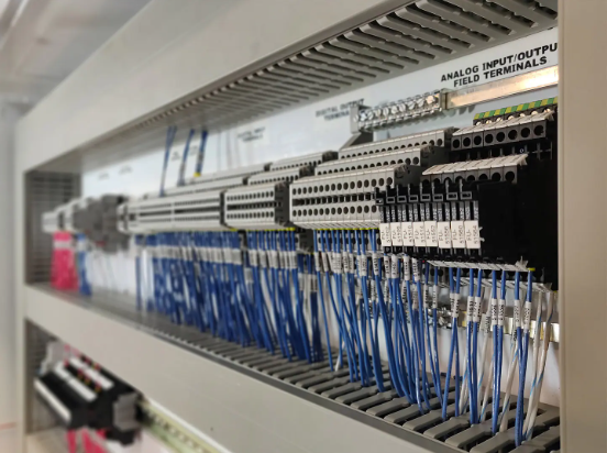
Module 6: Terminals & PLCs
- 6.1 Intelligent Terminals: Inserting and configuring terminal symbols. Setting terminal strip properties.
- 6.2 Terminal Strip Editor: The powerful tool for managing entire terminal strips, assigning wire numbers, and jumpers.
- 6.3 PLC Modules: Using the PLC Database File Editor to create custom PLC modules. Inserting parametric PLC I/O modules from major manufacturers (Allen-Bradley, Siemens, etc.).
- 6.4 Automatic Addressing: Using spreadsheets to auto-generate and import PLC I/O addresses.
Module 7: Automatic Reporting & Bill of Materials (BOM)
- 7.1 Generating Reports: Auto Cad Electrical Course in Visakhapatnam | Using the Reports tab to create various project-wide reports.
- 7.2 Bill of Materials (BOM): Generating a full BOM from the intelligent component data. Formatting the BOM table.
- 7.3 Other Key Reports: Creating Wire From/To reports, Component reports, and Cable reports.
- 7.4 Report Formatting & Exporting: Customizing report formats and exporting to Excel (.xls) or comma-delimited (.csv) files.
Module 8: Project-Wide Utilities & Error Checking
- 8.1 Project-Wide Update/Retag: The power of making changes across an entire project with a few clicks.
- 8.2 Electrical Audit: Running the audit tool to find common errors like duplicate wire numbers, unlinked components, and missing cross-references.
- 8.3 Title Block Update: Using the project-wide update tool to populate and update title block information across all drawings.
- 8.4 Copying Project Drawings: Using the “Copy Project” utility to safely duplicate a project and all its linked data.
Module 9: Customization & Standards
- 9.1 Symbol Builder: Creating custom schematic symbols and adding intelligence to them.
- 9.2 Footprint Builder: Creating custom panel layout footprints.
- 9.3 JIC/IEC/NFPA Standards: Understanding the different drawing standards and how to configure ACE to use them.
- 9.4 Template & Title Block Setup: Creating and configuring your own drawing templates and title blocks for company standards.
- Module 10: Capstone Project
- Auto Cad Electrical Course in Visakhapatnam | Students will design a complete control system for a simple machine (e.g., a conveyor system, a pump station).
- Project Requirements:
- Create a New Project: Set up the project file and drawing list.
- Schematic Design: Create a multi-sheet schematic including power, control circuits, and a PLC I/O diagram.
- Use Intelligent Components: Insert components with full catalog data.
- Apply Automatic Numbering: Use automatic wire numbering and component tagging.
- Implement Cross-Referencing: Ensure all contacts are cross-referenced to their parent coil.
- Panel Layout: Create a physical layout of the control panel with footprints.
- Generate Reports: Produce a Bill of Materials, a Wire List, and a Component List.
- Run an Audit: Perform an electrical audit to verify the design is error-free.
Recommended Tools & Version
- Software: AutoCAD Electrical: Auto Cad Electrical Course in Visakhapatnam | (Latest version or one version prior, available via Autodesk Education Community for free for students and educators).
- Resources: Manufacturer catalog databases, sample projects, and company-specific symbol libraries.
Learning Outcomes

Upon completion, students will be able to:
- Auto Cad Electrical Course in Visakhapatnam | Navigate the AutoCAD Electrical interface and understand its project-based, intelligent workflow.
- Create and manage an entire electrical project, not just individual drawings.
- Efficiently build multi-sheet schematic diagrams using ladder tools and intelligent components.
- Generate panel layout drawings that are dynamically linked to the schematic.
- Use automatic tools for wire numbering, component tagging, and cross-referencing.
- Create and manage PLC and terminal drawings.
- Generate accurate Bills of Materials and other reports directly from the design data.
- Perform project-wide updates and error checking to ensure drawing quality and consistency.
- Customize symbols and templates to meet specific company or project standards.
- Dramatically increase productivity and reduce errors compared to using standard AutoCAD.
Auto Cad Electrical Course in Visakhapatnam | This course is intensely practical, focusing on the automated features that make AutoCAD Electrical the industry standard for control system design. The capstone project is essential for demonstrating the powerful, time-saving workflow that integrates all the individual tools.